Brace Yourself!
Novel Uses for the Buckling Restrained Brace
By Kimberley Robinson, S.E.
Powerful and versatile! There are many applications for the buckling restrained brace.
Below are excerpts of an article printed in Structure Magazine in August 2012 and more from a 2014 NZSEE Conference Article.
The Buckling-Restrained Brace (BRB) was introduced in the United States in the late 1990s and since then has been used in nearly 500 structures. This technology has reached a significant level of maturity through research, codification and practice. The lateral-load resisting system in which it is an integral component, the buckling-restrained braced frame (BRBF), has been codified since 2005. However, many projects use the Buckling Restrained Brace in unique ways that differ from the standard BRBF concentrically braced frame. The braces have been used in or proposed for a variety of applications, including bridges, civil structures, horizontal diaphragm elements, highrise outrigger frames, externally anchored braces, wind towers and many other unique applications. The following projects show a sampling of some of the most innovative applications.
 Single Brace Retrofit
Rutherford & Chekene, a well-respected structural engineering consulting firm in San Francisco, was presented with a unique challenge on a steel and brittle concrete structure that they were asked to evaluate. This was a two story electrical substation that was built in the early 1900’s using steel framing and concrete shear walls. A renovation performed in the 1970’s removed the lower portion of one of the concrete shear walls. The resulting structure was not adequate to support the expected seismic demands.
Retrofit options were limited. Replacement of the concrete wall that had been removed was not an option, as the equipment that had been placed there was cost-prohibitive to relocate. Bracing on the exterior of the structure was not possible due to the historical nature of the structure. A singe brace could be allowed in the room adjacent to the area where the wall had been removed. A buckling restrained brace was selected as it was able to support both tension and compression loads while maintaining the required strength and ductility (see Figure 1). In addition, the brace could be “tuned” to match the stiffness of the remaining walls and reduce the possible torsion of the structure while reducing the size of the connections and the loads that needed to be transferred to the anchorages. A new collector and foundation was provided to complete this portion of the retrofit.
Highrise Outrigger System
The One Rincon Hill South Tower is a 60 story, 651 feet tall residential structure. It is located next to the western approach of the San Francisco – Oakland Bay Bridge. While being in the heart of one of the most seismically active regions in the US, the design was also governed by design considerations from powerful Pacific winds, which can reach hurricane force levels.
The design of the structure includes a concrete core for the seismic and wind forces. However, the length of the core in one direction was much smaller than the other direction. This created large overturning moments at the base and an increase in the potential sway of the structure in that direction. The design team at Seattle based Magnusson Klemencic Associates decided to incorporate outrigger columns into the structure to reduce the overturning forces at the foundation of the structure and to stiffen the structure in that direction, much the same as the use of ski poles can stabilize a skier. Bracing would be used to reach out to the outrigger columns to engage them at four levels of the structure (see Figure 2). Buckling restrained braces allowed the design team to limit the amount of load that would be delivered to the outrigger columns while controlling the stiffness and response of the braces. In addition, a large tank at the top of the building holding up to 50,000 gallons of water is used for two purposes: As a liquid damper to counter the sway from wind forces and as a reservoir for firefighting purposes.

 Bridge
The tallest bridge in California, the Foresthill Bridge, was determined to be in need of seismic retrofitting. This famous bridge, spanning the North Fork Canyon above the American River, was built in the early 1970’s and measures 2,428 feet from one side to the other. At more than 730 feet above the river, it is the fourth highest bridge in the United States and the ninth highest bridge in the world (see Figure 3). The bridge is a truss bridge and provides the primary link between the towns of Auburn and Foresthill, California. As part of the retrofit, the bridge is being widened to maintain traffic while the retrofit is taking place.
The engineering team at Quincy Engineering in Sacramento, CA completed the seismic evaluation and developed alternate retrofit solutions. The project included a very detailed project specific design criteria that was reviewed by a Technical Peer Review Panel and had very specific performance measures. There were multiple sets of ground motions that were based on a 1.0 peak ground acceleration. Through all of the detailed analysis it was determined that the BRBs provided the performance measures and allowed for repairable damage after a maximum credible event. The loads to be transferred to the longitudinal anchors of the bridge were required to be limited to protect the anchorage and move the inelastic deformations out to elements that could be replaced following a seismic event. Yielding of the BRB’s, in concert with other elements, ensured that the forces transferred to the superstructure did not exceed acceptable levels while still providing longitudinal stability.
 Horizontal Buttresses
Retrofitting of structures can create particularly difficult design challenges. When the structure being retrofitted is congested with piping and machinery that must stay in place, the level of complexity is increased. When the structure is a manufacturing facility that runs 24 hours per day and must stay in service during the retrofit, the design team is presented with opportunities for creative solutions.
The design team at Simpson Gumpertz & Heger were faced with such a project, which presented limited access to the interior of the structure. Part of the solution developed by the team included an exterior buttress frame of traditional bracing, which was designed to remain elastic during a seismic event, tied to the structure using horizontal buckling-restrained braces (see Figure 5). The braces were selected because they could deliver a specifically designed level of stiffness while limiting the maximum load to be transferred, providing ductility to the system. In addition, they would provide similar capacities in both tension and compression and were designed not to buckle at the design loads. Additional buckling restrained braces were included in the interior of the structure using traditional BRBF frames, including the use of a spliced BRB brace in order to erect the new brace around the obstacles encountered within the structure.

Externally Anchored Braces
Degenkolb’s engineers were faced with a similar problem. They, too, were working with a facility that could not be shut down during the retrofitting process. The externally anchored BRB system that was used provided for the retrofit of the structure with minimal disruption to the facility (see Figure 6). In addition, the bracing accommodated the aesthetical appearance of the structure that the architect envisioned. Larger bracing elements were provided than were required and connections were adapted to achieve the visual impact desired from the structure.
The projects listed above provide only a small sampling of unique uses for buckling restrained braces. As the brace usage expands, functions requiring symmetrical capacity between tension and compression, calibrated stiffness of elements, limiting of force transfer through an element and other features of the brace will continue to be found. The applications found truly demonstrate the abundant creativity of the engineering designers using the technology.

Brace Overstrength Factors
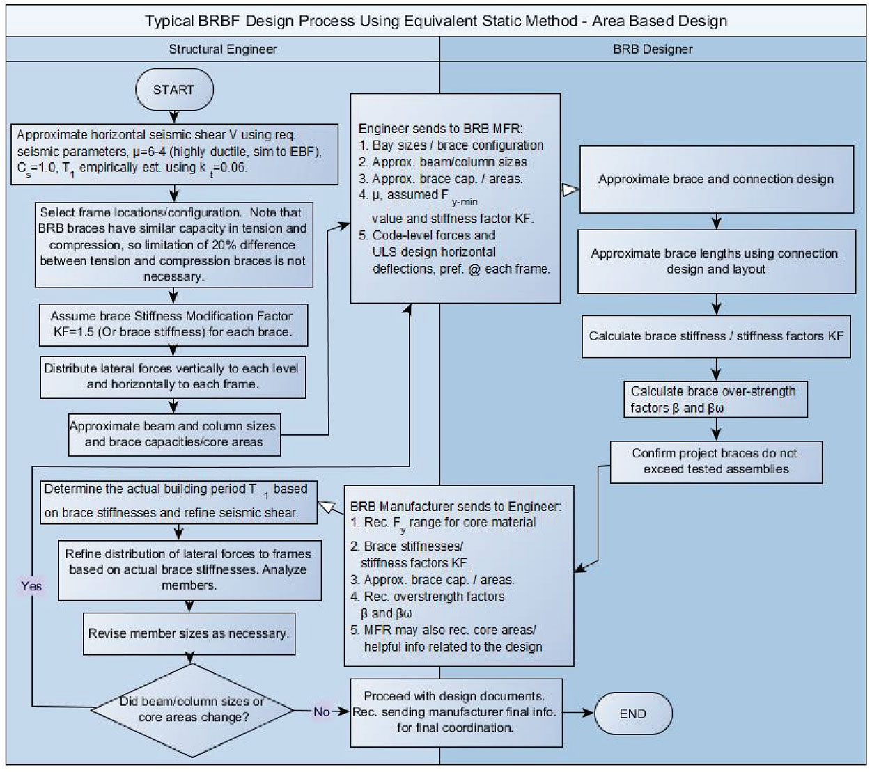
For the BRBF system, the brace is designated as the “fuse” element and all other parts of the frame and connections are designed to remain elastic. As the BRB brace engages in a seismic event, the steel core is designed to yield and then to strain harden. This process will require the beams, columns, and connections to be designed for these higher, strain-hardened brace forces. The increase in the brace force in tension is represented by the factor ω, while the increase in compression is represented by the factor βω. Using the AISC341 (US) test interpretation methods, factors can be determined from the results by use of a “backbone curve” drawn through the resulting peak values of the test data. Again, these factors vary by brace manufacturers and even by brace connection type. The engineer need not calculate these, as they can be provided by the manufacturer. These values are determined from the expected elongations in the braces. These may be determined by the BRB designer from the engineer’s drift analysis or simply through use of the design factors used by the design engineer. Following the drift analysis, the engineer may provide the BRB manufacturer with work-point to work-point elongations at each frame based on the final governing drift profiles of the frame. If these profiles include possible inelastic mechanisms, indicate this to the BRB manufacturer. Elongations determined directly from the amplified elastic deflections may require an additional factor of 2 to be applied to the brace strains, while elongations determined from possible mechanisms or those determined from inelastic analysis should not require this factor. Note that the use of inelastic drift alone to determine brace elongations may be overly conservative, since there are many contributors to drift from all the members of the frame (column elongation/shortening, beam distortion, etc) and the commonly used formulas to calculate brace elongation from drift assumes all the members in the frame besides the braces are infinitely rigid.
 Alleviate Building Pounding/Shear
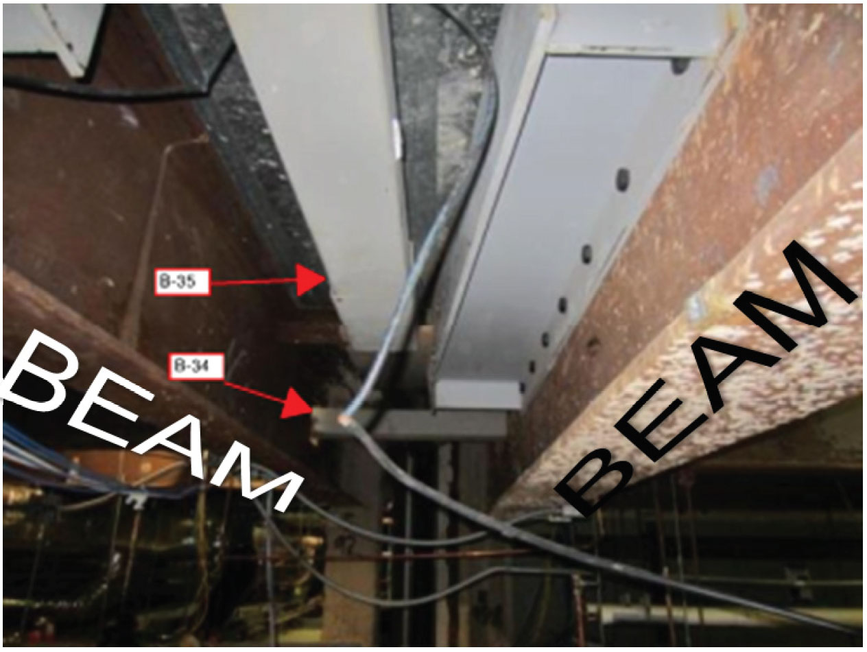
Often in retrofit construction, two buildings are located in close proximity and the pair of buildings may be expected to pound into one another and/or displace in such a manner that may potentially damage the piping or other equipment running between the two structures. The Veteran’s Administration Nursing Tower retrofit was such a project. Pairs of BRBs were employed to address these concerns and provide a shock absorber between the two structures to limit the damage that may be encountered. Refer to Figure 4. The two beams shown each belong to a separate structures, separated by an expansion joint but free to move independently from one another. Brace B-34 was added spanning between the two buildings to address pounding between the two buildings. Brace B-35 was also connected to each building, but was added to address shearing displacements between the two buildings. The analysis for the structural incorporated non-linear time history analysis and verified that the incorporation of the BRBs alleviated the concerns of the design team regarding damaging interaction between the two structures.

 High Rise Retrofit
In 1925, when it was completed, the Pacific Telephone and Telegraph Company structure at 140 New Montgomery was San Francisco, California’s tallest structure at 413 feet (125.9 m). The moment connections used in the original design were not adequate to achieve the performance objectives for the project. They did not have adequate stiffness to limit the drifts to an acceptable level given the brittle terra cotta façade. They also lacked the ductility needed for the performance desired. A new lateral system was needed to stiffen up the structure and protect the existing elements from excessive deformation and damage. The design team added a combination of BRBs and new shear walls. BRBs (shown below in red in Figure 5) were incorporated into “outrigger” truss systems. The BRBs provide both the strength and the stiffness needed to tie the new wall segments together, greatly enhancing the overall stiffness of the system. Unlike ordinary bracing, a BRB does not buckle and will limit the load that could be transferred to the rest of the structure, greatly reducing the forces that the rest of the structure would need to be designed for.
The projects used in this article represent projects from all three of the 2012 domestic BRB manufacturers. The author appreciates the input from each of the engineering firms listed, as well as Star Seismic, LLC., SIE, Inc. and Corebrace, LLC.